 Everyone gets hit with “aperture fever” at some stage and I’m no different. I had two 8 inch scopes (Newt & SCT) at different stages but found that I could see little of the objects I wanted visually unless I went to a dark site I moved to a 90mm APO to have a more portable setup that is suitable for photography.
The problem? Well, while the APO is a fantastic bit of kit I really missed being able to get nice views of some of the dimmer DSO’s at a dark site. The solution? Build my own scope. I have no DIY skills whatsoever so it seemed like an impossible task but there is so much information available on the web and in fantastic books, such as Kriege & Berry’s The Dobsonian Telescope, it actually turned out to be quite easy (if time consuming).
After much research the decision was made to build a 12.5″ F6 truss tube dobsonian. Why these specs? Here are a few of the points that pushed me in this direction:
- At 12.5 inches (or 325mm) the scope will have 2.5 times the light grasp of an 8 inch scope but will still be reasonably portable.
- At F6 the secondary obstruction can be kept small, this increasing contrast (one thing I hated about my SCT with it’s 30% obstruction). This scope ended up with a 17% obstruction – that’s smaller than a Mak’s!
- At F6 collimation will be far easier to maintain than on an F5 or F4.
- F6 will should give better performance for high power viewing out of the box (it didn’t for reasons described below).
- F6 also eliminates the need to use a coma corrector or very expensive premium eyepieces which could cost as much as buyig a new scope.
- There was a nicely priced secondary/primary/spider available on the used market
- No solid tube means no tube currents
- Trussed design will make it easier to transport the device as it will tear down
What are the cons? Here are a few:
- At F6 the observer will need a step or two to view at the Zenith.
- It will be less portable than a 12.5″ F4 or F5
- The secondary cage must be farther from the primary so it needs to be lighter than normal (or conversely the mirror box will need to be heavy – which is what happened in the end)
- Must be recollimated each time scope is rebuilt – not a problem as I did this with my SCT and Newt anyway
- Open tube is more susceptible to stray light – correctly baffling the scope makes this point redundant
Now that I knew what I wanted it was time to draw up a list of supplies (this list evolved as I went on and made changes, but here is the final).
- Primary & Secondary Mirrors
- Spider
- Focusser
- Finder
- Plywood (7 sheets @ 4’x2′)
- 1″ Aluminium Poles (Impossible to obtain so I used 3/4″ Chromed Steel)
- Router, Jigsaw, Drill & misc tools
- Strong wood glue
- Wood screws
- Various Bolts, Eyebolts, Threads
- Measurement tools, protractor, set square, t-square, rulers, pencils, + calipers (very important)
- Virgin Teflon
- Ebony Star Laminate or some similar alternative
- Springs to help balance (did not require these in the end)
- Shroud (provided by Michael O’Connell – Many thanks Michael!)
Measuring the Real Focal Length
Firstly the mirrors, spider & focusser were ordered. The primary was of 12.5″ F6 Oldham Optical stock. I have no stats on how good it is, such as wave accuracy, strehl ratio, etc, but it seems decent to me. Measuring focal length shows it to be closer to F6.1, having a focal length of 73 inches instead of 72 – this variance is quite typical and this is the first thing you need to measure before building your scope. To measure this just rest the mirror against a wall in your hallway or somewhere else that has plenty of room. Run a string from the base of the mirror down the room. Walk up and down shining a torch into the mirror while holding a piece of paper at the area of focus. As soon as the image focuses to a point note where you are by marking the string. Measure the distance to the beginning of the string and multiply by two – that’s your mirror’s focal length.
Optics Calculations
Next step was to design the optics train. This was particularly simple. You can download a program called NEWT that you plug the figures into & it will generate a ray diagram and show up any problems that may occur with focuser positioning, vignetting, etc. Plug in the values and go. The program spits out all of the relevant measurements, e.g. Primary to Secondary distance, Secondary to Focusser distance, etc.
Primary Cell and Holder
OK, still not done with preparation, we have some more calculations to make. This time it’s the primary holder. This may seem odd, hy not just sit the primary at the bottom on three pads to enable support & collimation? Not that simple really. We need to be able to support the mirror without deforming it. This 12.5″ is quite a thin mirror, being 1 inch thick. I think this would deform quite a bit without proper support. The anwer is to use a 9 point floating cell design similar to that used in many commercial scopes. This usually consists of a steel frame which supports three pivoting steel triangles, which in turn have three felt supports that the mirror rests on. Having no access to a metal worker and wanting to build as much of the scope as possible myself I looked into alternative methods, and found that a similar strength support could be build with 2×1 Oak for the main support + a circular ply mirror base using a very strong silicone based epoxy to replace both the triangles and the felt pads. The idea is that the points that would usually be pads would now be large dabs of adhesive, which acts both as a dampener and holds the mirror in place (no sling required). There would be nine dabs placed in the exact same places that the pads would normally sit. So how do we calculate where these dabs go? Simple, yet again some kind ATMer has built a software program to facilitate the task. Just download PLOP and plug your figures.
Once I had the figures it was simply a case of cutting out the support and attaching the mirror.
Lot more details to come, including the actual calculations, what bearing sizes to use, bearing materials and most importantly getting the centre of gravity corect. In the meantime here are some pictures of the build
Secondary Cage
{gallery}article_images/bigdob/SecondaryHolder{/gallery}
Mirror Cell and Cage
{gallery}article_images/bigdob/MirrorCell{/gallery}
Rocker and Base
I know I’ve left some shots out here, e.g. bearings construction. I’ll take some more shots and add them shortly
{gallery}article_images/bigdob/RockerAndBase{/gallery}
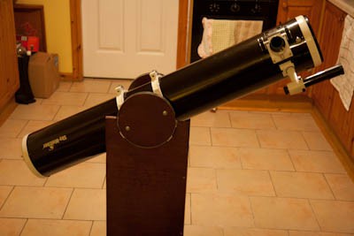
And the finished Article
{gallery}article_images/bigdob{/gallery}
There are no comments